
🔌 Power Up Smartly!
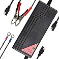
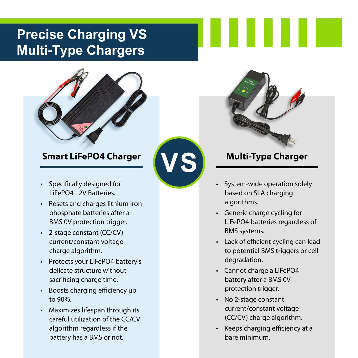
The ExpertPower 12.8V 5A Smart Charger is engineered for optimal performance with LiFePO4 deep cycle rechargeable batteries. Featuring a 2-stage CC/CV charging algorithm, it ensures efficient charging while protecting battery integrity. With a compact design and user-friendly LED indicators, this charger is perfect for both personal and professional use. Plus, it comes with a 30-day money-back guarantee and a 1-year hassle-free warranty.
| Manufacturer | ExpertPower |
| Brand | ExpertPower |
| Item Weight | 1 pounds |
| Product Dimensions | 2.5 x 1.8 x 1.8 inches |
| Item model number | EPC125 |
| Manufacturer Part Number | EPC125 |
K**M
Works well.
Works well. The clips for the charging cable and the charging cables themselves are a little underwhelming. Not sure about long term durability. It does the job though and the entire unit is small enough that it fits into my small radio bag without adding any serious bulk.
M**N
Modified to work as part of an uninterrupted power supply
My goal was to build an uninterrupted power supply for my Odroid single-board computers, which use between 19V and less than 12V depending upon peripheral devices. To that end I purchased an XZNY 20Ah LiFePO4 battery and this 5A charger, that does not throttle down to a lower voltage when the battery is full as others do, with the intention of modifying the output to 13.5V so that it will not damage the cells when left permanently connected. The charger instructions state that it should be disconnected after the battery is charged, which makes sense for preserving the capacity of the battery but may also be to preserve the charger components. Nonetheless I observed less than a watt (my instrument’s resolution) of quiescent power and I see no cause for concern in keeping it plugged into AC power. Someone else here mentioned that he modified his charger voltage (thanks packetrat!), so this charger seemed like a low-risk choice.I first opened the case, then pried up the circuitboard, sometimes using a knife to cut through the flexible glue used to hold it down. I then located the surface-mount LM324 quad operational amplifier and R104 (14.7k), which is the top half of a voltage divider (3k to ground on the bottom half) and is used to compare to a 2.5V voltage reference. I calculated that a 195k resistor in parallel with R104 would change the “battery full” voltage from 14.4V to 13.56V, but I wanted to chose that option with a switch, so I soldered wires at convenient places (see photo) that are equivalent to either side of R104. The other photo is of the switch: two 1% resistors in series (180k and 15k), and an ugly reworked solder job (I got it wrong the first time). If the voltage option were available through some fancy menu (it’s not), it might not remember the setting when the AC power is interrupted, so a simple toggle switch is best.When I started testing the charger as part of my uninterrupted power supply, I was dismayed that around 10W load (guesstimate) the fan would slowly turn on as higher charging current resumed. It’s loud. So I put in a replacement fan: 40mm, 12V, 14dBA, made by Scythe (SY124010L). Others may work better for less money. There is no 2-pin connector; it must be soldered in. What a difference! Now I can’t hear it at all. I’m sure there’s a little less airflow but I don’t expect a lot of heat buildup for my use case and I could never get the heatsinks very warm.Two weeks later and I have no complaints. The load is usually under 2 watts and the voltage is steady around 13.5V, perhaps a little lower depending on which DVM I use.
C**D
Great low amperage LiFePO4 charger
This charger is great, specially for slow charging if you have a large capacity battery. It does use constant current charging then the current decreases as the battery get closer to 100% charge. Good value, I recommend it. Does not get hot while charging. It does have a fan, not very noisy.
P**T
Charges well, but never seems to cut off completely
I've put this 5A model through several full charging cycles now, and it seems to work reliably, putting out slightly more than 5A into a deeply discharged pack, then tapering to 4A at around 2/3rds full, and 2.5A at an estimated 97% SOC.Based on "Cut-off Current: 0.3-0.7A" in the write-up, I expected this charger to disconnect from the battery once current dropped to that level, letting resting voltage fall to the ~13.6V expected of an LiFePO4 at 100% charge, but my 5A model never seems to. Instead, once the LED turns green it will just hold the battery at about 14.4V indefinitely (I let it go for 5 or 6 hours) as current tapers down to less than 0.01A (10mA). As far as I can tell, the green LED merely indicates that the charger has reached its voltage target, and shifted from constant-current to constant-voltage regulation mode.So, because it's not healthy for cells to remain at this elevated voltage indefinitely, you don't want to leave this charger attached to a pack for more than a few hours after reaching full charge.To pick another nit, the listing claims "Efficiency: 90%", but I measured 77-79% during bulk charging, using a Watts-Up DC meter on the output (cross-checked against a Fluke 189 ammeter) and a Kill-a-Watt on the AC input. For instance,5.18A*12.94V = 67.03W out; / 87W AC in = 77% efficiency (initial charge on deeply-discharged pack)4.00A*13.64V = 54.6W out; / 69W AC in = 79% efficiency when pack SOC is about 67%Not a huge problem, but worth noting. Maybe the 20A and/or 2A models do better, but burning a full ~20W internally at full output might help explain why this 5A charger needs a fan! Mine isn't obnoxiously loud, at least, and some people might appreciate the audible status indication - when that fan stops, you'll be at or above 90% SOC. Opening the case to service the fan, if needed shouldn't be difficult, with two screws on the bottom as pictured, but replacing it will involve soldering since there's no connector.I modified mine to reduce its maximum charging voltage from 14.4-14.5V down to 14.15-14.2V, to be a little easier on the cells (at the expense of slower charging from ~90-100%) and reduce the impact if I accidentally left it connected for a day or two. This requires removing the board (had to cut through some glue or epoxy holding it in at the edges), then soldering a 470k resistor across surface-mount R104 on the bottom, changing its effective resistance from 14.7k to about 14.25k. This is the top half of a voltage divider feeding one input of an LM324 opamp (3k to ground on the bottom half), which is compared to 2.500V from a TL431 precision reference for voltage regulation. Other sections of the LM324 appear to be for current limiting and fan control.
Trustpilot
2 weeks ago
1 week ago